Guide to getting started with your T-TRAK module kit
Before starting a YouTube search for ‘T-TRAK’ will provide a lot of information and ideas to familiarise yourself with the concept. Another excellent resource is http://t-trakhandbook.com/
Here's our video explainer:
Prior to assembling your module, lay out all the parts, familiarising yourself with them. A dry-assembly is very useful, to learn how the parts fit together before gluing.
Use a good quality exterior grade PVA wood glue, such as Evo-Stik ‘Weatherproof Wood Adhesive’, EverBuild ‘502’, or Gorilla ‘Wood Glue’.
Construction
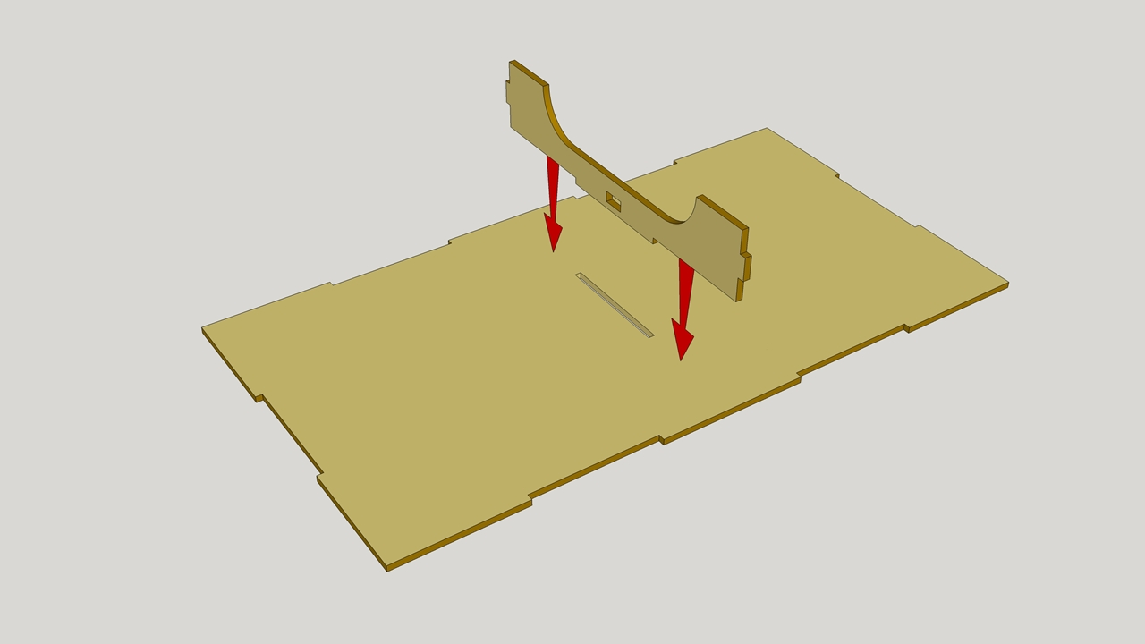
Place the top piece FACE DOWN with the track line (the front edge of the module) towards you.
Step 1
Glue in the central support(s) – there is one of these for the double module, two for the triple. There is no central support on the single module:
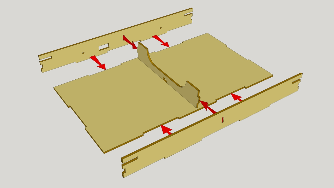
Step 2
Glue the rear board (the one with the rectangular cut-out in) into position – the engraved logo should be to the outside face – followed by the front board:
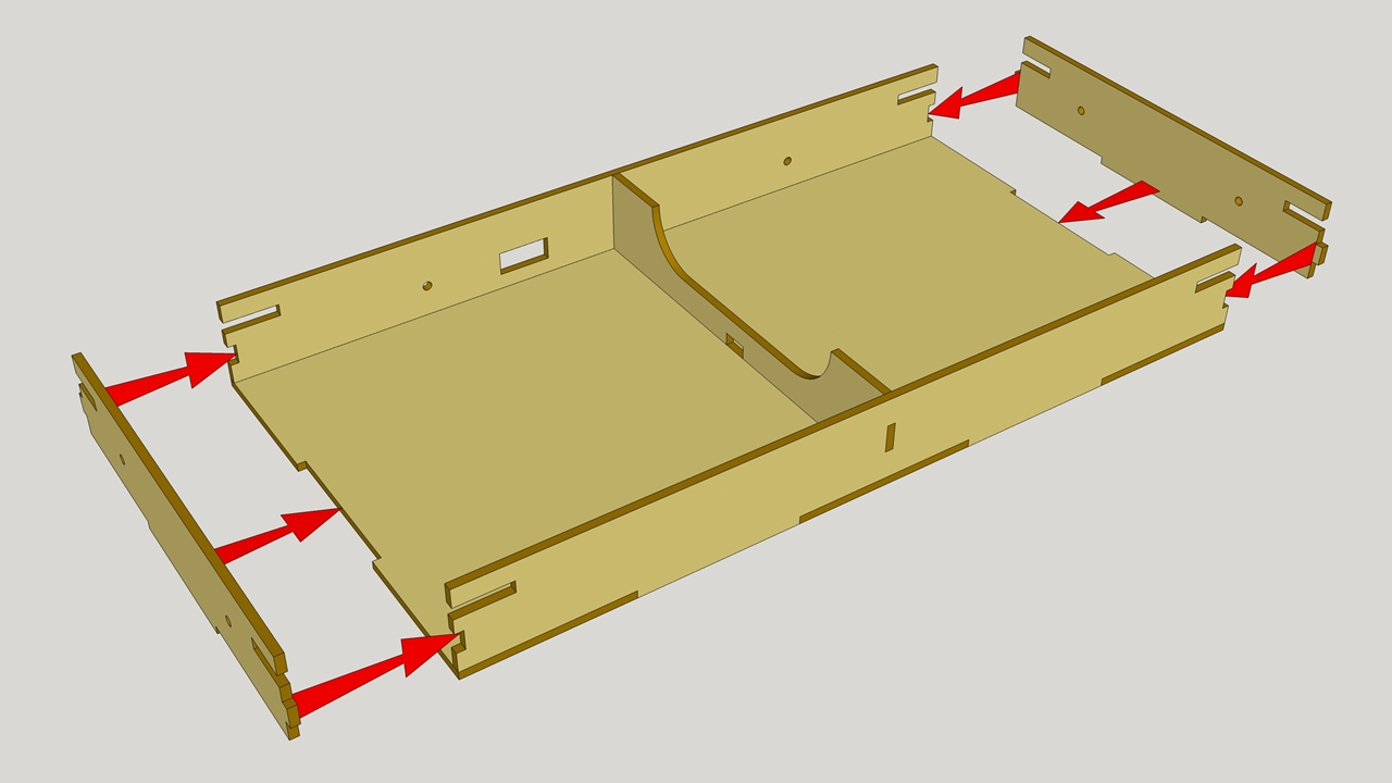
Step 3
Glue the end boards to the top piece and front & rear rails:
Clamp or tape the assembly, and leave to dry before proceeding.
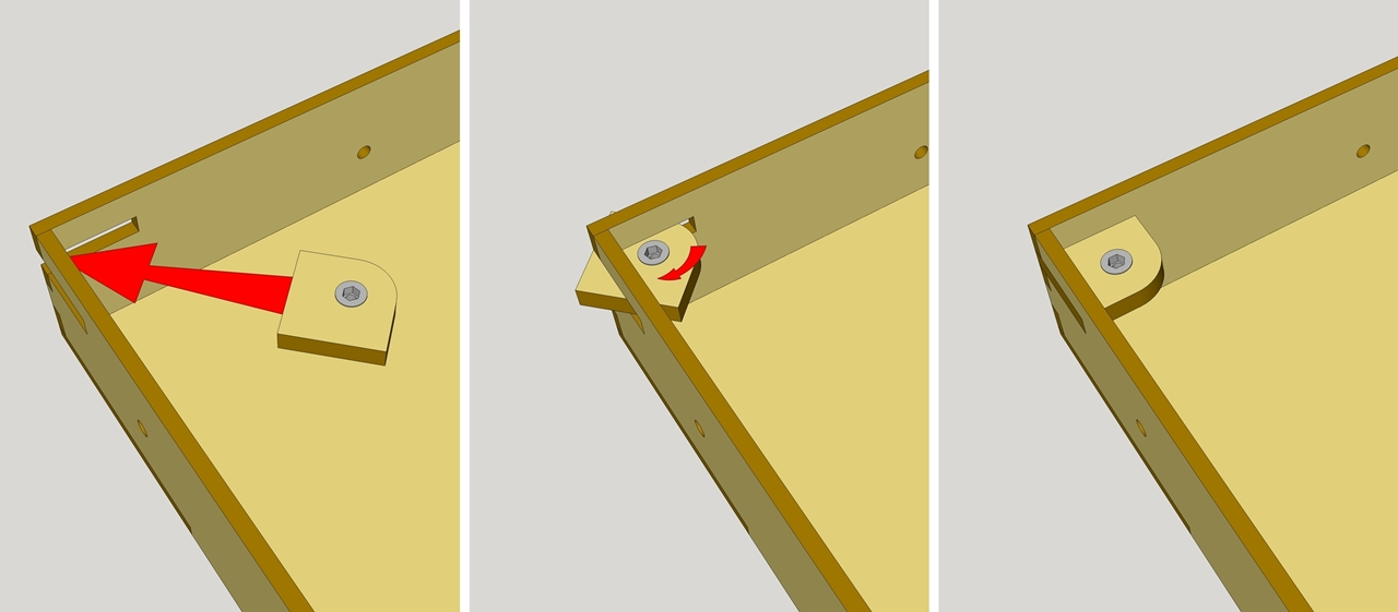
Step 4
Remove any tape/clamps etc, and then glue in the adjuster brackets. These already have the threaded inserts fitted to them, so need to be fitted from the inside at an angle, before rotating them and setting them flush with the outside edges. Ensure that the flange of the insert is facing upwards at this stage (so that when in use, the flange takes the weight of the module):
Alternatively, to install them from the outside, simply remove the inserts with a 6mm Allen key/hex driver. They can then be glued into position, and the inserts refitted.
This completes the glue-up of the main module parts. At this stage we would recommend sealing the plywood (including the backscene piece) with a matt varnish, prior to installing the feet, backscene, track, and electrics.
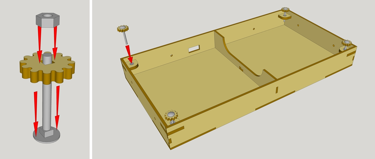
Step 5
Fit the thumbwheels (only included in the latest of our kits) to the M6 leg bolts, and secure with an M6 nut:
Track Laying & Power
For a straight (single, double or triple) module you’ll want the possibility of connecting power to the track. This isn’t straightforward on corners or junctions so you don’t need to include a power connector. All modules also get power via the uni-joiners on the rail ends.
There are a few ways to power the track, choose from:
Use Kato ‘24-818 Terminal Uni-Joiner’ to join your track sections (recommended)
Use Kato track power feed sections such as 20-041 62mm Feeder Track or 20-043 Double Track Feeder 62mm
Solder your own wires to the unijoiners (a Google search will produce plenty of how to videos)
Solder your own wires to the rail sides
After deciding on your method, drill any appropriate holes and test lay the outer track (nearest the front) on the board. The track bed should overhang by about 1mm on either side. The engraved line indicates where the edge of the outer track should lie.
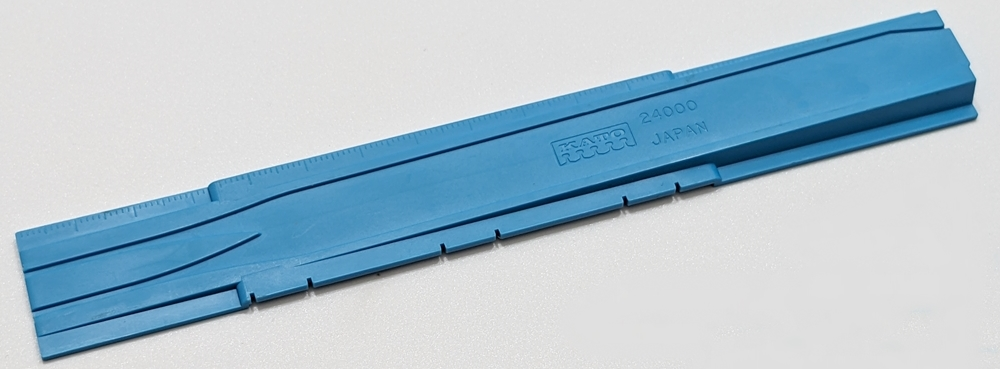
To get the correct track spacing at the board ends the most accurate is to use a short double track section (e.g. Kato 20-042) and connect both track ends to this. The Kato re-railer (24-000) can also be used a spacing guide – it has notches on the side which fit the rails at 33mm spacing:
When happy, secure the track to the board. To secure the track you can choose to:
Glue the track to the board. Be sure to use a glue that is suitable for both wood and plastic. Take care not to get glue on the rails.
Use track nails (Kato 24-015) – you may want to pre-drill the holes in trackbed and plywood.
Use small screws – use something like black anodised 1.4mm x 10mm woodscrews. Each Unitrack section has a moulded location(s) that can be drilled up from the bottom to create a hole in the trackbed. Be sure to drill a small pilot hole into the wood base to start the screws. Be sure you do not drive the screw below the natural surface of the track base. This will cause the base to bow inward narrowing the track gauge. If you can, countersink the Unitrack so the screws lie flat, and thus are almost invisible.
Connections
For the modules with power connectors, Yorkshire area group have settled on phono sockets rather than Anderson power poles as per the T-Trak specification. (Anderson power poles are easier to come by in the USA and considerably cheaper than here; the Australians also use phono sockets).
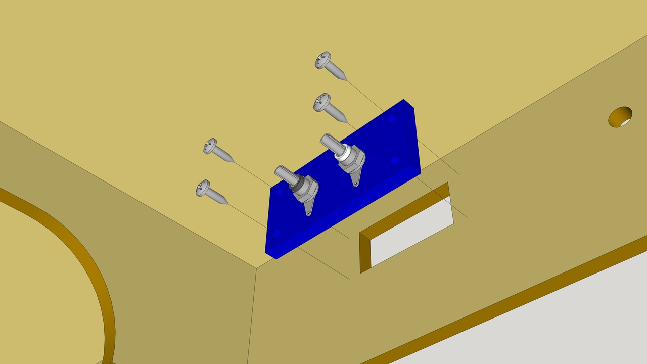
Modules are supplied with sockets and a small 3D printed plate to attach to the back of the baseboard. Fit the 2 phono sockets supplied (one white, one black) to this plate (the body of the socket goes in from the non-flat side; the solder tab goes on next, followed by the washer, and finally secured with the nut. The plate can then be screwed into the opening with the supplied screws. The plate goes on the inside of the baseboard, with the 4 small raised lugs in the inside corners of the cut-out in the plywood frame:
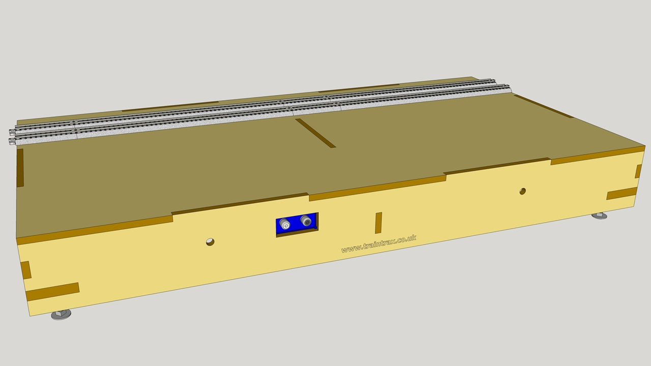
Though it is not critical, as the connectors are colour coded, it is good practice to install the white socket on the left (as viewed from the rear of the module) and the black socket on the right:
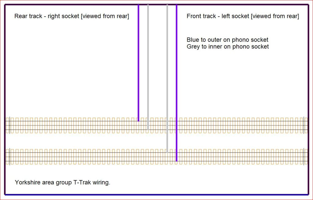
Wiring
To use phono connectors with a KATO connector you’ll need to cut off the ends of the KATO connectors and then re-solder to the phono plugs. No matter what method you use to connect the power, ensure you get the polarity correct as follows:
Track
Rail
24-818 Wire Colour
Rear Socket Connection
Front
Front
Blue
White socket outside ‘ring’ terminal
Front
Rear
White/Grey
White socket inside ‘tip’ terminal
Rear
Front
White/Grey
Black socket inside ‘tip’ terminal
Rear
Rear
Blue
Black socket outside ‘ring’ terminal
Note that this is the official T-TRAK 'BWWB' wiring standard – if you deviate from this, be aware that it WILL cause issues when attempting to use your module(s) with other modellers/groups!!!
Finishing Off
Attach the backscene with the supplied M6 x 20mm bolts and flanged nuts.
Apply your scenics of choice! Use you imagination to paint, carve, mould, cut, scatter, ballast and generally model a rural or urban scene. Do consider how the module will ‘fit’ with an unknown neighbour module – especially if altering the terrain.
I thought that might work too, but the designer assures me that the most precise way to align track is to connect to a piece of KATO double track. It's important that the alignment is correct for reliable connectivity.
That ensures the tracks aligned with each other, but not with the angle (i.e. they could be aligned using the double track piece but, say, 1cm too close to the front of the module. Or at an angle.


Leave a Reply